


The Earth's surface is not static, constantly shifting due to plate tectonics and crustal deformation. This continuous motion necessitates the use of dynamic global reference frames, such as the International Terrestrial Reference Frame (ITRF).
The Challenge of Global Coordinate Reference Frames: A Dynamic Earth vs. Static Frameworks
The Earth's surface is not static, constantly shifting due to plate tectonics and crustal deformation. This continuous motion necessitates the use of dynamic global reference frames, such as the International Terrestrial Reference Frame (ITRF). The latest iteration, ITRF2020, achieves millimeter-level precision. However, national/local coordinate systems typically rely on static frameworks tied to a specific historical moment (reference epoch). This creates a fundamental tension between real-time dynamic coordinates and local static coordinates.
Achieving centimeter-level positioning requires solving two core problems:
The GNSS data completeness rate refers to the ratio between the actual valid observation data received by a GNSS receiver within a given time period and the theoretical data that should have been received. It typically includes the following aspects:
- · Frame Differences: Mathematical differences in the reference ellipsoid parameters and origin orientations between coordinate systems.
- · Spatiotemporal Offsets: Drift in coordinates at a given location over time caused by crustal movement.
So how is the reference frame and epoch actually applied in surveying operations? Let's examine this from both relative and absolute positioning perspectives:
Relative Positioning (RTK / Post-Processing)
The rover’s reference frame and epoch are determined by the base station:
- · Set Base by Control Point: The rover inherits both from the control point.
- · Self-Starting Base: Derived from the broadcast ephemeris (limited “Single” solution accuracy; prioritize relative precision over absolute frame integrity).
- · VRS (Virtual Reference Station): Provided by the CORS network operator.
Absolute Positioning (PPP)
Tersus' TAP service broadcasts correction data containing precise ephemeris. Its framework is ITRF2020, with a real-time epoch. The service is continuously evaluated and optimized with ITRF updates to ensure its accuracy.
TAP to Local
Typically, RTK operates within a local coordinate framework, whereas TAP is based on the global reference framework. A common customer question arises: "TAP delivers high accuracy, but how do I obtain my required local coordinates?"
No worries! Tersus Nuwa Software seamlessly converts coordinates from the TAP framework to your local system.
Option 1: Dynamic Transformation (Recommended)
When the reference epoch and frame of your local coordinate system are well-defined, dynamic transformation (combining frame transformation and epoch reduction) can be applied.
Within Nuwa Software:
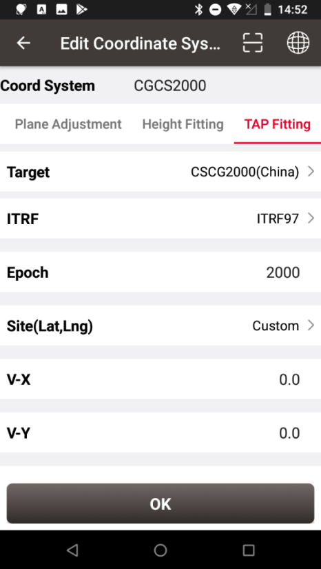
- · Navigate to the TAP Fitting section under Coordinate System settings.
- · Select the appropriate ITRF version.
- · Input the epoch information.
- · For the velocity field:
If known velocity data is available, input it directly (highly recommended).
If not, the software will automatically list the five closest reference stations' velocity fields based on your connected device's location for selection and calculation.
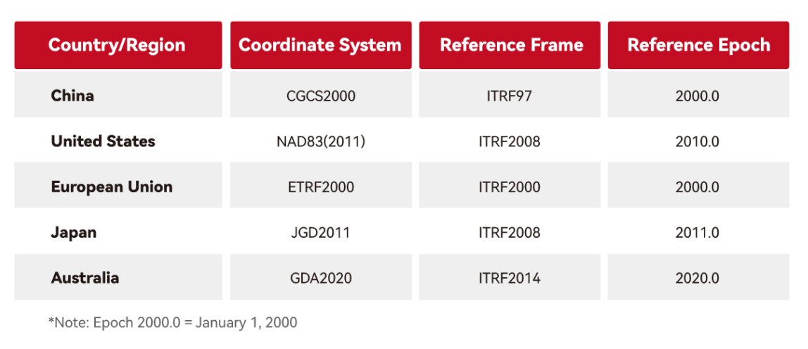
Global Reference Frame Examples
Option 2: Site Calibration (Control Point Transformation)
When the information required above is unavailable, static transformation (solving transformation parameters using control points) can be employed.
Static transformation offers the advantage of producing region-specific transformation parameters with strong local representativeness. However, it requires collecting multiple common points to solve the parameters. Due to inconsistent crustal deformation across large areas, this method is best suited for smaller regions. Larger areas necessitate partitioned transformation.
Tersus Nuwa software supports Site Calibration, calculating transformation parameters between TAP coordinates and your local system using control points.
Calibration Requirements
- · Horizontal: ≥ 2 points
- · Vertical: ≥ 1 point (increase for complex terrain)
- · Validation using independent check points
Common Customer Question: "Can I calibrate with just one point? What's its effective range?"
Answer: Technically yes, but the usable radius of a single point is difficult to determine. A rule of thumb is 10 km, possibly 15 km on plains, maybe less than 3 km in rugged terrain.
The fundamental principle of their "zone of influence" – where effectiveness diminishes with distance – stems from the amplification of error propagation. This "control radius" represents the critical distance where precision degrades beyond acceptable thresholds, determined by required accuracy, terrain complexity, receiver performance, etc.
Option 3: TAPFill Intelligent Switching
Tersus further enhances resilience with TAPFill technology, which bridges positioning continuity through intelligent framework maintenance.
When RTK/VRS signals are interrupted:
When the reference epoch and frame of your local coordinate system are well-defined, dynamic transformation (combining frame transformation and epoch reduction) can be applied. Within Nuwa Software:
- · Auto-Switch: Leverages satellite-delivered TAP corrections to maintain centimeter-level positioning
- · Frame Continuity: Computes real-time transformation parameters through synchronous RTK-PPP observation
- · Intelligent Recovery: Automatically reverts to the original framework upon signal restoration
TAPFill automatically utilizes satellite-broadcast TAP corrections to bridge positioning gaps caused by cellular network failures or radio link loss. By analyzing concurrent RTK and PPP observations, it dynamically calculates transformation parameters between the two frames and converts TAP coordinates to the RTK framework in real-time. Through satellite-delivered independent corrections and intelligent switching, TAPFill minimizes operational downtime, ensuring uninterrupted surveying and reliable data continuity during signal outages.
Tersus TAP Technology: Your Triple-Layered Solution for Global-to-Local Coordinate Challenges.
Combining Dynamic Transformation, Site Calibration, and TAPFill, TAP seamlessly tackles coordinate conversion dilemmas. Whether confronting tectonic drift, signal outages, or parameter gaps, it delivers precise, project-ready coordinates – ensuring streamlined workflows and enhanced efficiency for every survey.

