


The positioning stack behind the products
Proprietary GNSS silicon, an in-house RTK/PPP engine, global corrections and sensor fusion with vision and LiDAR — developed at Tersus since 2014.
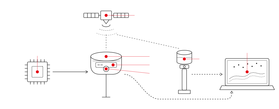
Signal to deliverable
Antares™ SoC → ExtremeRTK™ engine → TAP™ PPP corrections → visionRTK™ / TightSLAM™ fusion → capturRTK™ reconstruction
Antares™
GNSS SoC
TAP™ PPP
GNSS constellation · L-band / IP corrections
ExtremeRTK™
RTK engine
visionRTK™
Visual-inertial positioning
TightSLAM™
GNSS/IMU-anchored SLAM
capturRTK™
Georeferenced reconstruction
MVP Engine
Office reconstruction
Red markers show where each technology lives in the hardware and software chain.
Technologies
01
Antares™
Proprietary GNSS SoC
Tersus designs its own GNSS system-on-chip: signal tracking, multipath mitigation and the RTK engine run on silicon Tersus controls, which is why receiver performance can be tuned for high-accuracy surveying applications and for machine control in challenging environments.

02
ExtremeRTK™
Positioning engine
Multi-constellation, multi-frequency RTK with fast re-acquisition under canopy and near structures. Patented work in signal tracking, multipath mitigation and GNSS/IMU fusion.

03
TAP™ PPP
Global corrections
Satellite- and IP-delivered PPP corrections, no base station and no radio link. Converges to under 3 cm horizontal in under 5 minutes under open sky (95 % confidence).

04
visionRTK™
Visual-inertial positioning
Tersus has pioneered the integration of camera-based visual odometry, visual SLAM and GNSS/INS on a survey rover to maintain a usable position where satellites drop out, under canopy, beside structures, in urban canyons.

05
TightSLAM™
GNSS/IMU-anchored SLAM
Fuses GNSS and IMU data directly into the SLAM pipeline, anchoring 3D spatial data to real-world coordinates instead of estimating it from imagery alone, so mapping stays survey-accurate underground and between high-rise buildings.

06
capturRTK™
Georeferenced reconstruction
On-device mesh and point-cloud generation with RTK constraints, producing georeferenced deliverables rather than a floating scan.

07
MVP Engine
Simultaneous localisation and mapping
Real-time LiDAR and visual SLAM engine that builds dense, georeferenced 3D maps while the operator walks. Fuses IMU, GNSS and camera data for centimeter-level accuracy indoors and outdoors.

Our Newsletter, right to the point
Product updates, case studies, tech articles and industry news.